
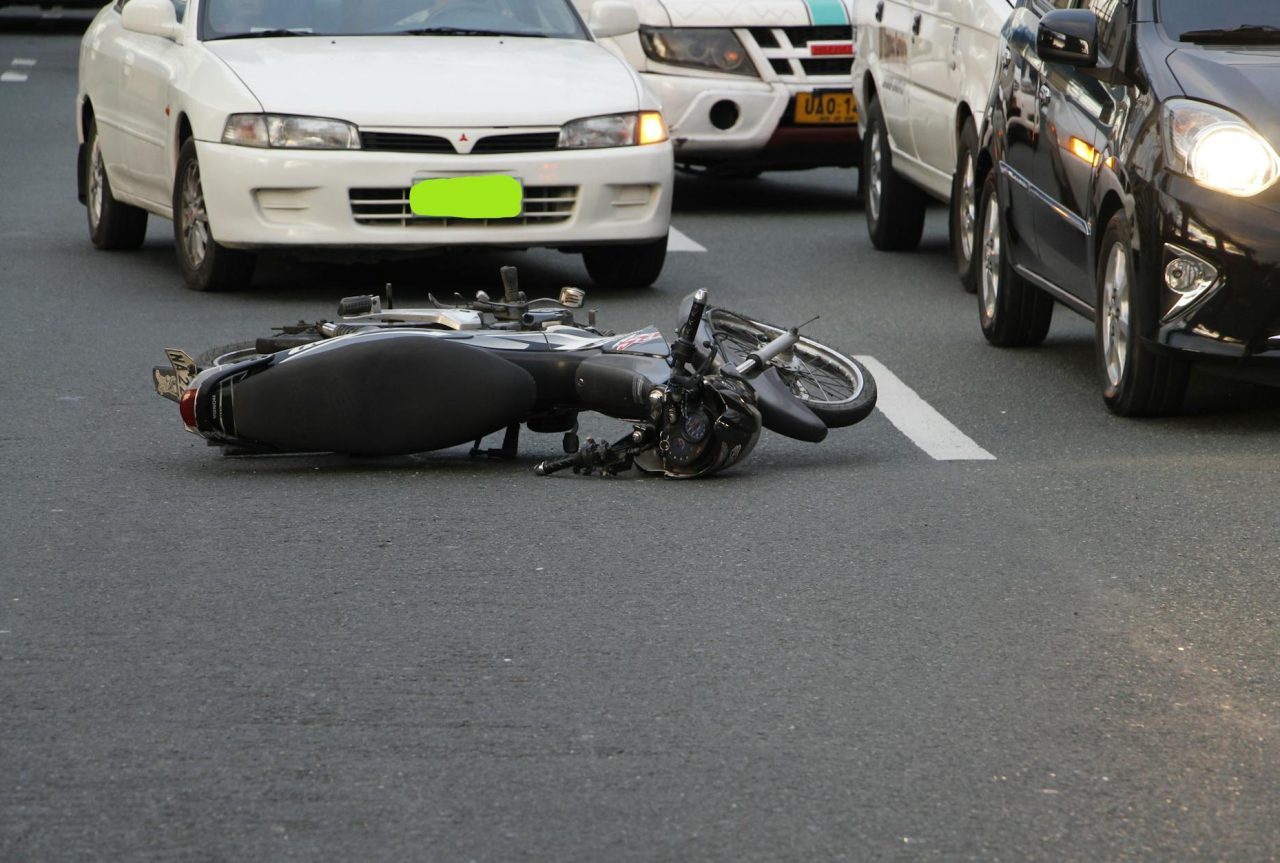
Traffic light recognition failures are not hypothetical: they create hesitation, incorrect right-of-way decisions, and crashes when vehicles or drivers misread signals. Low-angle sun can wash out colors in the span of a few seconds; a single power transient can take controllers offline for hours.
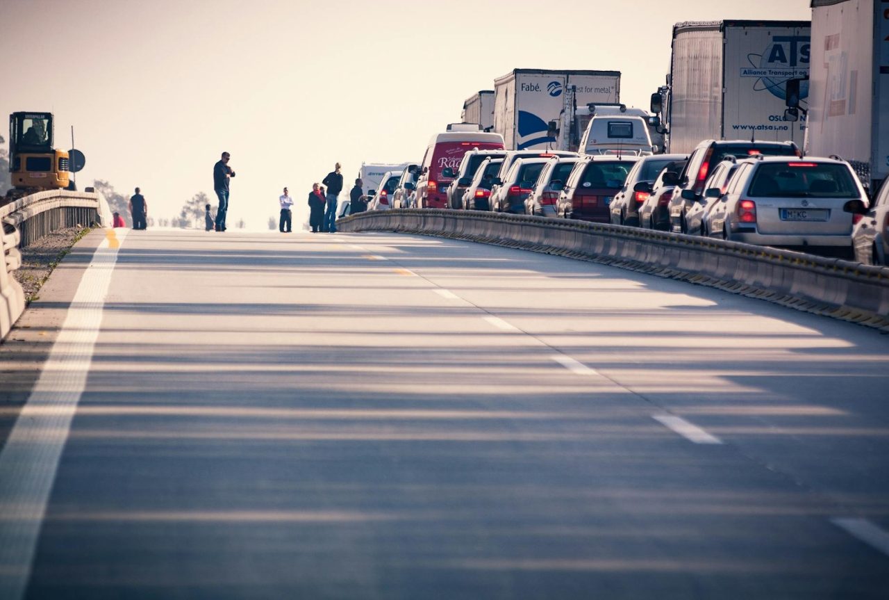
Glasgow’s power spike that knocked traffic controllers into fault modes produced stuck and flashing lights, widespread delays, and required crews to manually direct intersections—a blunt reminder that electrical events cascade into street-level hazards.
Real incidents and documented attacks: what they show about risk
Two clear patterns emerge from incident reports and research. First, infrastructure faults (power spikes, aging controllers, damaged loops) cause visible, immediate disruption and require manual action.
Second, laboratory and field research shows camera-based TLR can be manipulated by optical inputs—lasers and structured-light projections—that cause classifiers to flip states.
Those research results are practical: portable lasers and projectors can create effective spoofing vectors against some camera+ML stacks.
Decision factor: infrastructure failures tend to be local and blunt (lights stuck, flashing), while optical spoofing targets vehicle perception and is stealthier. Both need different mitigations—hardening and procedures for controllers, and sensor fusion plus adversarial detection for vehicles.
How do traffic light recognition pipelines actually work?
Most TLR pipelines in connected and autonomous vehicles use camera imagery processed by detection and classification models, often fused with map data and V2X.
- Image capture: monocular or stereo cameras at 20–60 fps provide the raw visual feed.
- Preprocessing: color correction and region-of-interest cropping reduce the search space.
- Detection and classification: neural models find signal heads and decide phase (red/yellow/green, arrows).
- State fusion: classifier output is combined with GNSS-mapped signal locations, V2X phase messages, and radar/lidar presence checks.
- Decision layer: planner issues control commands or driver alerts based on fused confidence.
Why this matters: Cameras read color and symbols directly but are vulnerable to glare, saturation, or optical injection. Map and V2X provide redundancy but assume accurate infrastructure state and secure comms.
Where systems break: failure modes and root causes?
Power, controllers, and field hardware
Power spikes, transient overvoltages, and aged power supplies can damage signal controller electronics or cause repeated reboots. Glasgow’s incident showed how a single grid event can produce a city-level disruption. Common hardware failure points include blown surge suppressors, corroded connectors, and thermal-stressed PCBs in controller cabinets.
Diagnostics: measure supply rails with a multimeter and handheld oscilloscope to capture transients; inspect connectors and seals for corrosion; check controller logs for repeated reboots. Surge arrestors and small UPS units reduce outage exposure and are often worth installing at busy intersections.
Field detectors and wiring
Inductive loops, video detectors, and radar each have failure modes: loops fail after pavement cuts; video struggles in fog and glare; radar can register false positives from nearby metal. Wiring faults produce intermittent detector signals that lead to timing errors and extended greens or phantom phases.
Perception: misclassification, occlusion, and optical attacks
Camera-based perception can be stealthily wrong. Misclassification occurs when neural nets see bright reflectors, advertising LEDs, or car taillights and vote for a false signal. Occlusion by trucks, scaffolding, or foliage removes the signal from view. Research demonstrates that carefully directed lasers or patterned projection can push a classifier across its decision boundary.
Why classifiers fail: models generalize from training distributions. Rare lighting angles, lens flare, sensor saturation, or intentionally crafted optical inputs create out-of-distribution images that produce high-confidence errors. That mismatch is the attack surface researchers exploited in recent VehicleSec work.
System-level faults: communications, timing, and software
Lost or delayed V2X messages, controller timing mismatches after maintenance, and firmware bugs all create ambiguous states. For example, if V2X broadcasts say ‘green’ but the camera and local detector disagree, planners must choose a conservative action or risk a wrong maneuver.
Diagnostics at this layer require correlating controller logs, detector occupancy timestamps, and vehicle telemetry. Without synchronized logs and secure time-stamping, root cause analysis stalls.
Practical diagnostics and tools for technicians and fleet operators
Safe troubleshooting follows a hierarchy: avoid live work unless qualified, collect logs, run non-contact checks, then escalate to powered tests.
- Basic toolset: multimeter, handheld oscilloscope (for transients), thermal camera, and a CAN bus reader to correlate vehicle streams with perception outputs.
- Imaging checks: use RAW frame histograms and a colorimeter or software histogram to spot clipped channels, channel shifts, or saturation patterns indicative of glare or photodetector damage.
- Controller checks: inspect cabinet seals, measure upstream supply quality, and review firmware version and signed update status.
When to call a professional: multiple controller reboots, burnt or swollen components, persistent color shifts in camera images, or unexplained phase changes require certified technicians. On vehicles, consult a certified shop for camera recalibration or sensor replacement; DIY attempts often leave subtle misalignment or insecure mounts.
Vehicle-level backups and fail-safe strategies
Vehicles should assume sensors will fail or be spoofed occasionally. Design for conservative safety under uncertainty.
- Sensor redundancy: at least two camera viewpoints (primary and angled secondary) plus map and inertial data. You’ll feel at home if one camera is obscured, but the other has an offset angle.
- Temporal voting and short consensus windows: require consistent detections across 3–5 frames at 20–30 fps before acting; balance latency against responsiveness.
- Cross-modal downgrades: if camera output conflicts with map or V2X, default to slow and yield. For automated vehicles, that usually means stopping at the limit line and waiting for resolution if uncertainty persists for 2–4 seconds.
- Adversarial detection: monitor for high-intensity, narrow-spectrum inputs and pixel-level saturation patterns. Photodiode-based laser detectors or frequency-domain checks reduce spoof success but produce false positives in sun-glare—tune thresholds to local conditions.
- Driver interface: expose a clear ‘uncertain signal’ flag on the HUD with an explicit takeover instruction. What people miss: many stacks hide confidence metrics; a simple, visible uncertainty prompt is far more actionable than a buried log entry.
Trade-offs and limits: more sensors and higher-frame-rate cameras reduce failure risk but add cost, power draw, and computational load. Temporal voting reduces false positives but increases reaction time; pick windows that match intersection speeds and stopping distances.
Infrastructure backups that reduce single points of failure
Hardening controllers and detectors brings large safety returns at vulnerable intersections.
- Power protection: fit surge arrestors and a small UPS (500–2,000 VA) to hold controllers long enough to switch to the generator or manual control; UPS cost ranges with capacity, so prioritize trafficked sites heavily.
- Detector diversity: combine inductive loops with video and radar in high-exposure locations; detector diversity lowers total downtime from any single mode failure.
- Secondary controllers and secure updates: dual-controller configurations and signed firmware updates reduce the chance of a single-point controller fault or a compromised update causing city-wide issues.
- Manual response plans: clear SOPs for police or signal teams, portable stop signs, and temporary traffic lights. Run practice drills every 6–12 months; Glasgow’s crews needed on-site routing and manual control to restore order quickly.
Decision factors: budget and political will constrain how much redundancy a city deploys. Prioritize intersections with high pedestrian flows, transit routes, or known electrical exposure for immediate upgrades.
Adversarial threats and mitigations
Attack vectors against camera-based TLR include narrow-beam lasers and structured-light projections that change the apparent color or add synthetic signal geometry. Countermeasures that work together provide the best protection:
- Spectral and polarization filters to reduce narrow: spectrum laser input.
- Photodiode or dedicated optical: spoof sensors for fast detection of laser pulses.
- Multi-sensor fusion so that a spoof affecting only cameras does not drive decisions alone.
- Multi: frame consistency checks and plausibility checks against mapped signal phases or V2X state.
Limitations: No single countermeasure is perfect. Spectral filters reduce scene brightness in some lighting; photodiode detectors need careful tuning to avoid sun-glint false positives.
Realistic scenario with decision trade-offs
Scenario: At 8:10 a.m., the low sun creates glare on the primary camera. The primary classifies the signal as ‘unknown’ while a V2X message and the angled secondary camera indicate green. The vehicle’s policy requires a 3-frame consensus or V2X confirmation. Because the secondary camera matches the V2X state, the planner proceeds; if the secondary disagreed, the car would conduct a controlled stop.
Why this matters: single-sensor failure would have caused either an unsafe go or an unnecessary stop. The fusion policy reduced false stops while preserving safety, but it depended on accurate V2X and the presence of a usable secondary camera.
Common mistakes
Over: relying on visual TLR without map/V2X backup—creates a single point of failure.
- Using very long temporal voting windows indiscriminately causes excessive latency at intersections.
- Failing to log gray: area events and anomalous frames—without logs, root cause analysis stalls.
- Assuming flashing signals are uniformly safe—flashing red and flashing amber carry different legal meanings; treat them conservatively.
Safety warnings and final practical guidance
Safety first: do not attempt high-voltage work on signal cabinets without qualified personnel. Never disable or modify vehicle safety systems without consulting the manufacturer. If you suspect a vehicle TLR failure, switch to manual driving, stop before the crosswalk, and proceed cautiously.
Small lived-in observations: you’ll notice glare problems spike at certain times of year as the sun angle changes; a thermal camera often finds a failing power supply before any visible fault appears; skip long temporal voting delays at busy arterials—they cause backups. A common field anecdote: technicians often find a corroded connector after intermittent signal timing complaints, not a software bug.
Read Next: Cybersecurity risks in self‑driving cars — prevention strategies
Read Next: Software update delays — how OTA solves it?
Read Next: Lane merging problems — cooperative driving solutions