Introduction — why sensor blind spots threaten safety and which risks matter most
Sensors in autonomous cars observe different physical properties: cameras capture color and texture, LiDAR maps geometry, and radar senses motion through RF reflections. Each has gaps. When blind spots occur—objects undetected, mislocated, or mischaracterized—an AV’s planner can brake late, make an unsafe lane change, or miss a vulnerable road user. Here’s the catch: adding sensors reduces some blind spots but increases cost, complexity, and new failure modes.
What people miss is how mundane objects cause disproportionate trouble. A low plastic bag snagged on a lane marker may vanish to radar, produce a sparse LiDAR spike, and look like road litter on camera until it’s too late. The practical goal is not zero risk but focused mitigation where blind spots create real danger.
How the main sensors create and hide blind spots
Understanding why blind spots exist makes fixes clearer. Below are the core sensing modalities, their strengths, limits, and the failure modes that matter for design decisions.
Cameras — detail with limited depth and lighting sensitivity
Cameras deliver dense2D images that are strong for classification: signs, traffic lights, clothing contrast. Limits: depth ambiguity beyond stereo baseline, high sensitivity to glare and low light, and occlusion. Specular reflections from wet surfaces or glass can saturate pixels and hide objects. Expect reliable recognition in many production systems out to roughly30–80 m depending on optics and compute.
LiDAR — accurate range, but sampling gaps and reflectivity limits
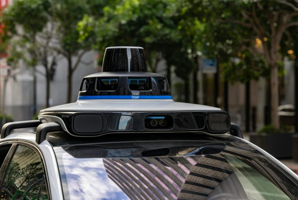
LiDAR provides3D point clouds and precise ranges. Blind spots come from vertical coverage, angular resolution, and material reflectivity. Sparse scan patterns can miss small, fast, or low objects between beams. Dark, absorptive materials return few photons, creating partial or missing detections. Frame rates vary—mechanical units often run5–20 Hz; some solid-state designs trade density for higher frame rates.
Radar — robust in weather but coarse and angle-dependent
Radar measures range and radial velocity and works through fog and rain. Its angular resolution is coarse, and specular reflections create ghost targets or dropouts at shallow incidence angles. Low-profile objects—plastic debris, curbs, some bicycle frames—can produce weak echoes. Higher-bandwidth, MIMO systems improve resolution but increase cost and regulatory complexity.
Why a multi-modal approach is non-negotiable
No single sensor eliminates all failure modes. Combining camera detail, LiDAR geometry, and radar velocity reduces many blind spots but leaves scenarios—like low-contrast small objects or particular reflection geometries—where perception will be uncertain unless mitigated by placement, software, or infrastructure.
Common real-world blind-spot scenarios to prioritize
Occlusion by parked vehicles: delivery vans, or roadside clutter that hides pedestrians and cyclists until close.
- Specular and retro-reflective environments (glass façades: wet roads) that generate spurious returns or mask targets.
- Sensor-geometry blind cones created by bumpers: A-pillars, or roof racks that leave short-range gaps.
- Material: dependent dropouts from matte black plastics or carbon fiber that return few LiDAR photons and weak radar echoes.
- Adverse weather: LiDAR backscatter in heavy rain or snow, camera contrast loss at dusk, and noisy radar returns in cluttered urban settings.
- Low: small, or fast objects—animals, debris, or curbs—that slip between beams or under thresholds.
Engineering fixes that reduce blind spots and their trade-offs
The solid engineering response layers hardware, software, and operational controls. Below are practical choices, why they work, and when they might not be worth it.
Sensor placement and overlapping fields of view
Place sensors to create overlapping azimuth and elevation coverage so a single occlusion doesn’t produce total loss. Practical rules:
- At critical angles (front: sides, rear) use at least two sensors with overlapping FOVs. Two low-mounted cameras that point the same way are not redundancy if both share the same blind cone.
- Raise some sensors (roof LiDAR: high cameras) to see over vehicle roofs and parked obstacles; you’ll feel at home if you accept slightly greater vulnerability to physical damage and higher mounting torque specs.
- Combine narrow: long-range optics with wide-angle near-field sensors to cover both detection and classification tasks.
Multi-modal fusion and principled redundancy
Fusion choices affect behavior under uncertainty. Early (raw-data) fusion preserves cross-modal cues but costs compute and demands tight calibration. Late (decision-level) fusion isolates modality failures but loses some corrective power. Design fusion to output explicit uncertainty—covariances or calibrated confidence—so planners can act conservatively when perception is ambiguous.
Calibration, self-checks, and in-field monitoring
Precise extrinsic calibration is essential. Automated in-field checks that detect static landmarks—curbs, signposts, lane markers—can monitor reprojection error and flag maintenance. Practical thresholds: reprojection error rising beyond about0.5–1 pixel or range errors of2–5 cm at20 m should trigger investigation. Tight thresholds reduce intermittent blind-spot behavior.
When hardware upgrades are the right decision
Higher-channel LiDAR (128–512 channels) and denser radar arrays reduce sampling gaps and angular blind zones, but cost and energy budgets rise sharply. Upgrade when fleet data show recurring failures tied to sparse vertical coverage or when mission profiles require reliable detection of small, low objects (e.g., delivery robots or scooters in dense urban cores).
Software countermeasures that buy safety margins
Software cannot recover information a sensor never captured, but it can manage risk and create conservative behaviors that prevent catastrophe.
Perception, scene priors, and occupancy reasoning
- Apply scene priors: higher pedestrian probability at crosswalks and sidewalks. Soft priors let the system infer occluded objects without hard assumptions.
- Use implicit occupancy grids to represent likely object presence in occluded cells, integrating motion history and map semantics. Temporal smoothing reduces phantom obstacles from noise.
- Train ML models with adversarial and occluded examples to reduce blind-spot surprises, but monitor for overfitting and dataset bias.
Explicit uncertainty modeling and conservative planning
Feed perception uncertainty into the motion planner. Practical rules:
- If lateral or longitudinal uncertainty exceeds thresholds: reduce speed and increase buffer distances—slow to a crawl near occluded driveways.
- Require multi-frame: multi-modal confirmation before committing to risky maneuvers like lane changes: consistent detections across two consecutive frames and across modalities before executing.
Runtime sensor-health detection and fallbacks
Monitor frame-drop rates, SNR trends, and cross-modal discrepancies (e.g., radar reports velocity but LiDAR points absent). Trigger graded fallbacks: reduced-capability driving, pull-over to a safe stop, or remote-operator handoff. False positives reduce usability; calibrate thresholds using fleet telemetry and real-world trials.
Infrastructure and cooperative sensing for persistent gaps
On-vehicle hardware plus software still miss line-of-sight hazards. Infrastructure can extend perception beyond physical limits, but rollout and maintenance are the trade-offs.
Roadside units and V2X augmentation
Roadside radar or LiDAR units can cover occluded intersections and blind corners—place them at complex junctions and busy pedestrian zones. V2X can broadcast cyclist presence or pedestrian alerts from phones or RSUs. These systems work well in pilots but require secure, low-latency links and agreed maintenance responsibilities. Design systems to degrade gracefully when infrastructure is absent.
Map-aided sensing and priors
High-definition maps provide persistent priors—curb lines, lane geometry, and sign positions—that reduce localization-induced blind spots. Use maps to bias perception and occupancy expectations but do not hard-code behavior that assumes perfect map accuracy; maps age and environments change.
Diagnostics, maintenance, and when to consult a specialist
Many blind-spot incidents begin with preventable maintenance issues. Regular diagnostics keep sensors within spec and reduce intermittent failures.
Common failure points and tool requirements
- Contamination: mud, salt, ice, and road spray on housings reduce returns. Hydrophobic coatings and scheduled cleaning help but do not replace inspection.
- Mechanical drift: vibration and minor impacts loosen mounts and change extrinsic calibration. Check torque on sensor mounts after5,000–10,000 km or after any impact.
- Sensor aging: emitter power and detector sensitivity decline, especially for laser diodes and infrared detectors—track SNR trends and retire units before safety margins erode.
- Software regressions: updates can reduce detection sensitivity for edge classes—use continuous integration with targeted edge-case datasets.
Tool requirements: torque wrenches sized for sensor mounts, optical targets for laboratory recalibration, and diagnostic software that logs SNR, point counts, and reprojection error. Safety warning: always isolate power and follow lockout procedures before working on sensor housings; high-voltage emitters and moving parts can present hazards.
Quick maintenance checklist
| Task | Frequency | Why it matters |
|---|---|---|
| Visual housing inspection | Every1–2 weeks | Catch dirt, cracks, and water ingress before detection degrades |
| Automated calibration health check | Daily at startup | Detect extrinsic drift from vibration or impacts |
| Signal-quality logging (SNR, frame drops) | Continuous | Spot gradual degradation earlier than visual checks |
| Full recalibration | Every6–12 months or after impacts | Restore geometric alignment and perception accuracy |
If reprojection errors exceed configured thresholds (for example, persistent error >1 cm at10 m) or LiDAR point counts drop >30% without environmental cause, consult a professional mechanic or sensor specialist. Water inside housings, cracked optics, or structural mount damage require shop-level tools and expertise.
Validation and testing that prove blind-spot resilience
Safety is demonstrated by tests that exercise edge cases, not by marketing claims. Testing should combine simulation, hardware-in-the-loop, and miles in the real world.
Scenario-based and edge-case testing
- Create test permutations of occlusion: lighting, and weather with recorded sensor traces to validate perception responses.
- Use hardware-in-the-loop to simulate LiDAR dropouts: radar specular reflections, and camera glare to exercise fallbacks without risking people.
- Field tests with instrumented drivers remain necessary to uncover rare blind-spot events that simulation misses.
A common observation in fleet trials: a2–3 second delay at occluded urban turns is socially acceptable and prevents high-risk assumptions; skip aggressive clearance heuristics in those scenarios.
Example scenario — left turn at an occluded urban intersection
Context: mid-sized AV approaches a left turn where parked vans block the view of oncoming traffic. System design: roof LiDAR, side radars, and a roadside radar unit feed fused perception with explicit uncertainty. The planner reduces speed, waits for a transient radar Doppler signature that matches a bicycle, and requires camera/LiDAR confirmation across two frames before committing.
Outcome: the vehicle waits3–6 seconds for confirmation—an acceptable delay compared with assuming the lane is clear. Trade-offs: infrastructure-assisted detection reduces risk but requires reliable communications and maintenance agreements.
Common Mistakes
Assuming two sensors automatically provide redundancy: if their fields overlap poorly they can share the same blind cone.
- Neglecting small maintenance tasks—dirt: a loose screw, or minor housing cracks lead to outsized perception errors over time.
- Relying solely on ML confidence without cross: modal sanity checks; models can be confidently wrong on out-of-distribution objects.
- Deploying V2X: dependent features without robust degradation modes; systems must be safe when infrastructure is absent.
Safety warnings and tool notes
Work on sensors only after isolating power and following lockout/tagout procedures. Use non-abrasive cleaners for optics and hydrophobic coatings specified for automotive sensor grades. Tighten mounting fasteners to manufacturer torque specs; overtightening can crack housings and undertightening leads to drift. If recalibration requires a rooftop jig or laser tracker, schedule service at a qualified facility.
FAQ
How much do higher-end sensors reduce blind spots?
Higher-channel LiDAR and multi-element radar arrays reduce geometric and sampling blind spots substantially by increasing vertical coverage and angular resolution. They do not eliminate reflectivity-related dropouts or occlusion; upgrade when fleet data show repeated misses tied to sparse coverage, and budget for increased power and thermal management.
Can software alone make blind spots safe?
Software improves safety margins via uncertainty modeling, conservative planning, and occupancy inference, but cannot recover data a sensor never captured. Software is most effective when combined with sensor diversity, deliberate placement, and disciplined maintenance.
Are roadside radar and V2X practical today?
Roadside units and V2X work well in pilots and targeted deployments—complex intersections and high-pedestrian areas are good starting points. The main limits are scale, funding, and standardization; design AV behavior to degrade safely when V2X is unavailable.
When should I pull a vehicle from service for sensor issues?
Pull from service if automated checks report persistent calibration errors beyond thresholds (e.g., reprojection error >1 cm at10 m), if LiDAR point counts drop >30% with no environmental cause, or if water/condensation appears inside housings. Also remove vehicles when perception-confidence falls repeatedly for common object classes during normal driving.
Practical conclusions and next steps for engineering teams
Shrinking sensor blind spots requires targeted investments: sensible sensor placement, explicit uncertainty in fusion, disciplined maintenance, and selective infrastructure where it yields the most benefit. You’ll get the most return by prioritizing fixes that address frequent, high-consequence failures observed in fleet data rather than blanket hardware upgrades. A tight maintenance program, routine calibration checks, and scenario-based testing will prevent most avoidable blind-spot incidents.
One short, commonly observed anecdote-style moment: teams often find that a single dirty LiDAR window or a loose bracket, unnoticed for weeks, explains a string of errant detections across multiple trips. That small fix is worth the inspection time.
For further technical background on sensor combinations and their limits, consult specialized reviews on AV sensing and automotive blind-spot systems. Also see the internal resources on perception best practices for integration and fleet diagnostics.
References
- WARNING: Objects in Driverless Car Sensors May Be …
- The Importance of Vehicle Blind Spot Detection Systems – Hesai
- A Difficult Drive: Autonomous Vehicle Sensor Limitations
- How Automated Vehicles See What's Around Them – Car and Driver
- Blind spot detection – Bosch Mobility
Image Credits
- Pexels: Stephen Leonardi – source
- Pexels: ThisIsEngineering – source
- Pexels: Sergey Meshkov – source
Read Next: Traffic light recognition failures — backup systems explained